CentrioleJ is a user-friendly ImageJ [1] plugin that we have developed to process images of centrioles. It mainly consists of two steps, circularization and symmetrization, that we describe in more detail below.
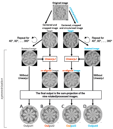
The observed centriole often resembles more an ellipse than a circle. However, it is not known whether this reflects the real centriolar shape or is due to e.g. the fixation procedure. In CentrioleJ, we allow the user to circularize the centriole prior to further processing (i.e. make it circular rather than elliptical). Then, during symmetrization, CentrioleJ enhances the features in the image that show the presumed symmetry (e.g. 9-fold). In a nutshell, symmetrization consists in rotating the source image according to its symmetry and sum-projecting all the rotated images. See Figure 1 for an overview of the different processing possibilities in CentrioleJ.
|
|
| Fig.1 | Applying CentrioleJ on a Chlamydomonas probasal body observed in cryo-microscopy. (A) Output of the sum-projection of the 9 rotated images without correction (the rotation angle is a multiple of 360°/9=40°). Note that the microtubule triplets are not well visible. (B) Output after re-aligning the rotated images using UnwarpJ [2] and taking the unrotated image as the target (=reference). (C) Output after circularization and UnwarpJ re-alignment. (D) Output after circularization only. Note that the outputs B, C and D nicely show the pinhead and the microtubule triplet. These outputs are very similar because the source image was not very noisy and that the centriole was almost circular. In general, the outputs B, C and D will be less similar. |
Circularization
In order to circularize the input image, the user should draw a polygon with vertices at the A microtubules (Fig. 2A, yellow line). ImageJ will then fit an ellipse to this polygon and extract its orientation (angle θ) as well as its major and minor axes (a and b, respectively; see Fig. 2B). The input image is then rotated by an angle 90-θ counter-clockwise (Fig. 2C). Lastly, the input image is rescaled along the x- and y-axis. Assuming that the deformations along one axis necessarily yield a compensatory deformation along the other axis, we impose that the perimeter of the initially fitted ellipse and resulting circle (of radius r) should be equal:
![]()
Hence, the image is scaled by a factor r/b along the x-axis, and r/a along the y-axis, resulting in the circularized centriole (Fig. 2D).
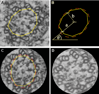 |
| Fig.2 | Circularization of the centriole. Once the user has picked the A microtubules using the polygon tool (A), an ellipse is fitted to extract the orientation θ as well as the major and minor axes (B). The centriole is then rotated by an angle 90-θ counter-clockwise (C) and re-scaled by a factor r/b along the x-axis and r/a along the y-axis (D). |
Symmetrization
CentrioleJ also takes advantage of the presumed symmetry SYM of the centriole, as specified by the user (typically 9-fold). Hence, the (circularized) centriole is recursively rotated by an angle i*360°/SYM , with i running from 1 to SYM-1. The rotated images are then re-aligned one-by-one to the reference, unrotated, image using the plugin UnwarpJ [2] (elastic registration). Note that the user can also specify landmarks on the centriole to be used by UnwarpJ. Finally, the SYM resulting images are sum-projected to yield the symmetrized centriole.
References
- Schneider CA, Rasband WS, Eliceiri KW (2012) NIH Image to ImageJ: 25 years of image analysis. Nat Methods 9: 671–675.
- Sorzano COS, Thévenaz P, Unser M (2005) Elastic registration of biological images using vector-spline regularization. IEEE Trans Biomed Eng 52: 652–663. doi:10.1109/TBME.2005.844030.